DS18B20 Raspberry Pi Setup - What's The Deal With That Pullup Resistor?
2019-06-12 - By Robert Elder
In this article, we'll review the setup steps for using a DS18B20 thermal sensor probe with a Raspberry Pi and also attempt to clarify some confusion related to the external pull-up resistor that is sometimes used with this sensor. You can also view the video that complements the content in this article below:
Before discussing the software-based steps for using this sensor, let's resolve an important question that you're likely to have in relation to how you wire up your probe: Do you really need the external (usually 4.7K) pull-up resistor between the data line and the power? If you're using a newer Raspberry Pi (or an Arduino) the answer is No. The short story is that you can use a software control inside the Raspberry Pi to take advantage of an internal pull-up resistor that is inside the Raspberry Pi.
The longer explanation involves the details of the '1 Wire Protocol' that is used for communication by the DS18B20. The typical DS18B20 sensor comes with 3 pins/wires exposed: Ground, Data and power. One feature of the 1-wire protocol is that it allows you to get rid of the dedicated power wire and instead power the chip directly from the 'data' line. This works because the 1-wire protocol dictates that when idle, the 'data' line should be put high to logic 1, and DS18B20 comes with a tiny capacitor that stores enough energy that allows it continue to operate when the data line is low during communication. As a result, we need a pull-up resistor either to 'pull up' the power pin voltage near the voltage of the data line (when you want to avoid running a 'power' wire), or to pull up the data bus to logic 1 when it is idle if you decide to use a power wire, but don't want to use the internal pull-up resistor in the Raspberry Pi.
Here is a picture of my working setup that avoids the use of any soldering or pull-up resistors (exposed bare copper wires not recommended):
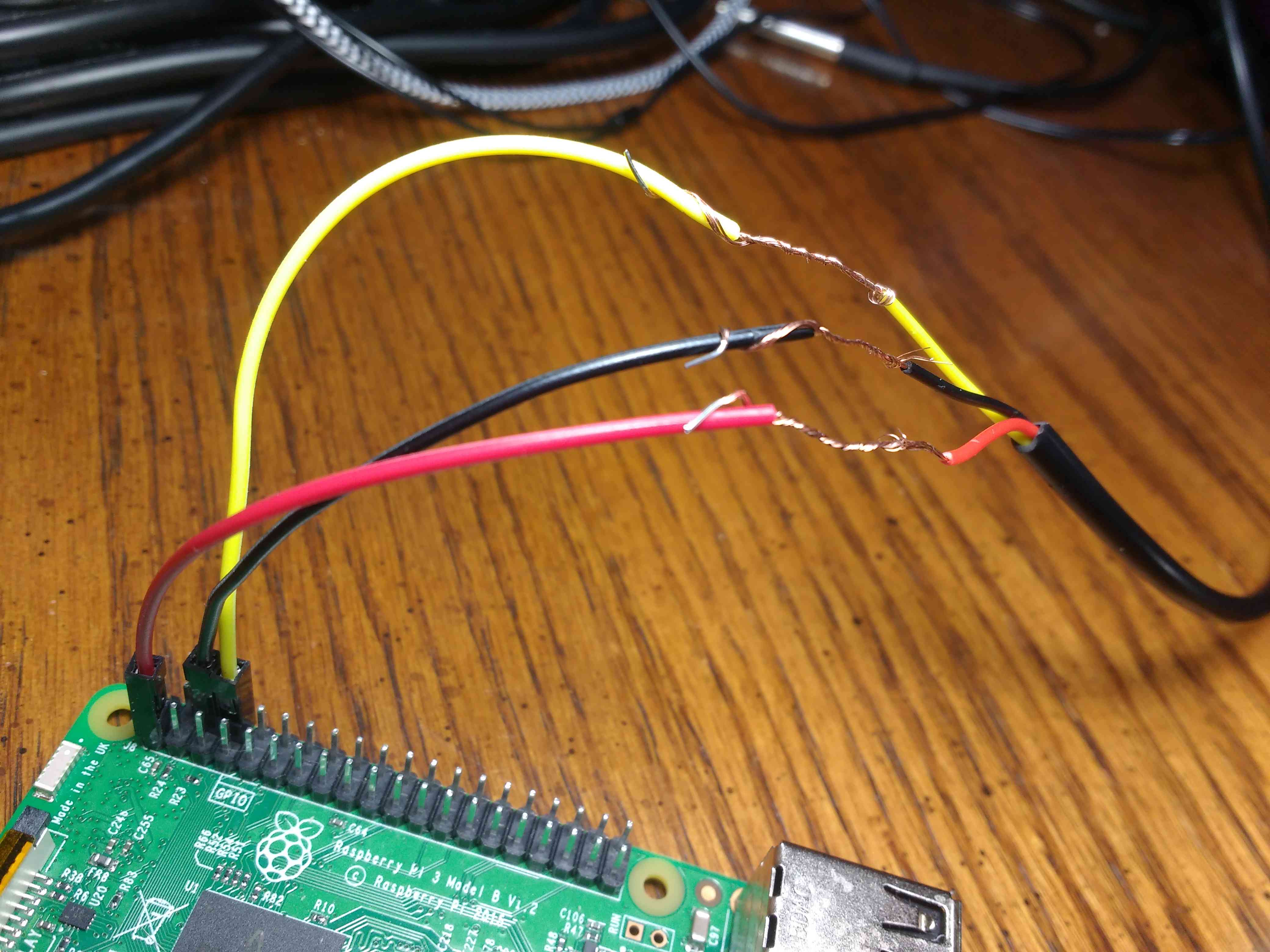
In the picture above, red is attached to 3.3v, Black is attached to ground, and Yellow is attached to GPIO14 (in your case, you can use a different GPIO pin). Now, before you get too excited, note that will have to do a few setup steps before you can actually read from the sensor. First, add the following to the end of your /boot/config.txt file:
dtoverlay=w1-gpio,gpiopin=14
Take care to replace the '14' in the line above with the number of whatever GPIO pin you've attached the data line (yellow) to. Use can use the 'pinout' command to see a view of the GPIO pin numbers. Also, be sure not to confuse the 'GPIO number' with the 'pin number' (they are different concepts). Once you've added this to the boot config, reboot your Raspberry Pi. Also, you can read documentation about the 'dtoverlay' feature and its syntax by running this command:
cat /boot/overlays/README
Next, you'll need to make sure that the kernel modules 'w1_therm' and 'w1_gpio' are currently active. Run this command to check if they're already running:
lsmod | grep w1
If you see output like this, then these kernel modules are already active:
w1_therm               16384  0
w1_gpio                16384  0
wire                   45056  2 w1_gpio,w1_therm
In my case, I found out that these modules were already built into the kernel and enabled by default, so I didn't need to turn them on with 'modprobe' or install them into '/etc/modules'. I was able to find them by running:
find /lib/modules/$(uname -r)/ | grep "w1_therm\|w1-gpio"
If not you can activate them using these commands:
sudo modprobe w1_therm
sudo modprobe w1_gpio
Note, however, that 'modprobe' will only enable these modules until the next reboot and then you'll need to run 'modprobe' again. If you want them to be enabled at boot, run these commands to add them to /etc/modules:
sudo sh -c 'grep "w1_therm" /etc/modules || echo "w1_therm" >> /etc/modules'
sudo sh -c 'grep "w1_gpio" /etc/modules || echo "w1_gpio" >> /etc/modules'
Reading Values From The Sensor
With the wiring I've shown above, you first need to enable the pull-up resistor on the GPIO pin 14. Here is some Python code that does this:
import RPi.GPIO as GPIO

GPIO_PIN_NUMBER=14
GPIO.setmode(GPIO.BCM)
GPIO.setup(GPIO_PIN_NUMBER, GPIO.IN, pull_up_down=GPIO.PUD_UP)
You'll need to run the above python code after each reboot before you attempt to read from the sensor. I tried to use the boot overlays config file to find a way to do this at startup, but all of the methods I tried didn't seem to work.
2023-04-05 Update I received an email from someone today who said "The way I solved it, was by editing the /etc/rc.local and adding: sleep 15 && /home/pi/pull_up_boot.py". I have not independently taken the time to verify that this works, but I'll leave this note here for anyone who may benefit from it.
At this point, your Raspberry Pi should now be able to detect the sensor. You can check by doing:
ls /sys/bus/w1/devices/
If your sensor was detected, you'll see a unique id number like '28-0214816276ff'. This id number is a directory that should contain a file called 'w1_slave'. Check its contents to do a temperature reading:
cat /sys/bus/w1/devices/28-0214816276ff/w1_slave
Here is an example of the output when it works:
ab 01 4b 46 7f ff 0c 10 20 : crc=20 YES
ab 01 4b 46 7f ff 0c 10 20 t=26687
The number '26687' in the output above is the temperature reading in thousandths of a degree celsius, so this reading says 26.287 ° C. However, the accuracy is stated to only be +/- 0.5 ° C. Here is a handy script I created to parse out the information and also detect a few common error cases:
# -*- coding: utf-8 -*-
import glob
import time
import os
import sys

#  An Example Reading from /sys/bus/w1/devices/<ds18b20-id>/w1_slave
#  a6 01 4b 46 7f ff 0c 10 5c : crc=5c YES
#  a6 01 4b 46 7f ff 0c 10 5c t=26375

import RPi.GPIO as GPIO

#  Set Pullup mode on GPIO14 first.
GPIO_PIN_NUMBER=14
GPIO.setmode(GPIO.BCM)
GPIO.setup(GPIO_PIN_NUMBER, GPIO.IN, pull_up_down=GPIO.PUD_UP)

def ds18b20_read_sensors():
  rtn = {}
  w1_devices = []
  w1_devices = os.listdir("/sys/bus/w1/devices/")
  for deviceid in w1_devices:
    rtn[deviceid] = {}
    rtn[deviceid]['temp_c'] = None
    device_data_file = "/sys/bus/w1/devices/" + deviceid + "/w1_slave"
    if os.path.isfile(device_data_file):
      try:
         f = open(device_data_file, "r")
         data = f.read()
         f.close()
         if "YES" in data:
           (discard, sep, reading) = data.partition(' t=')
           rtn[deviceid]['temp_c'] = float(reading) / float(1000.0)
         else:
           rtn[deviceid]['error'] = 'No YES flag: bad data.'
      except Exception as e:
         rtn[deviceid]['error'] = 'Exception during file parsing: ' + str(e)
    else:
      rtn[deviceid]['error'] = 'w1_slave file not found.'
  return rtn;

while True:
  temp_readings = ds18b20_read_sensors()
  for t in temp_readings:
    if not 'error' in temp_readings[t]:
      print(u"Device id '%s' reads %.3f +/- 0.5 °C" % (t, temp_readings[t]['temp_c']))
  time.sleep(1.0)
When I run this script, I get the following output:
Device id '28-031724836eff' reads 27.062 +/- 0.5 °C
Device id '28-031724836eff' reads 27.937 +/- 0.5 °C
Device id '28-031724836eff' reads 29.125 +/- 0.5 °C
Device id '28-031724836eff' reads 29.875 +/- 0.5 °C
Device id '28-031724836eff' reads 30.562 +/- 0.5 °C
Device id '28-031724836eff' reads 31.000 +/- 0.5 °C
Device id '28-031724836eff' reads 31.312 +/- 0.5 °C
Device id '28-031724836eff' reads 31.562 +/- 0.5 °C
Device id '28-031724836eff' reads 31.812 +/- 0.5 °C
Troubleshooting Notes, Pull-up Resistor Fun & Parasite Power Mode
I made a valiant attempt to demonstrate that this probe does work in parasite power mode, but I was never able to get it work. I eventually found a this thread where many other people expressed difficulties getting this probe to work in parasite power mode on the Pi. Some people mentioned that the internal pull-up resistor inside the Pi has a very high resistor value (much higher than the 4.7K mentioned in the DS18B20 documentation). It was suggested that this high resistor value prevents the sensor form being able to draw enough current to power itself. Instead, people suggested using a pull-up between the GPIO on the Pi and the 3.3v power on the Pi. I did some experiments with this, and again, I wasn't able to get it work in parasite power mode. For pull-up resistor values between about 2.2k and 4.7 between the GPIO and 3.3v, I was able to get the sensor in a mode where attempting to read from it would take a long time (just as it does when it works correctly), but the reading that came back was always '0':
pi@raspberrypi:~ $ cat /sys/bus/w1/devices/28-0214816276ff/w1_slave
00 00 00 00 00 00 00 00 00 : crc=00 NO
50 05 4b 46 7f ff 0c 10 1c t=0
For all other pull-up resistor values, it would detect the sensor, but immediately return the value '85' every time:
pi@raspberrypi:~ $ cat /sys/bus/w1/devices/28-0214816276ff/w1_slave
50 05 4b 46 7f ff 0c 10 1c : crc=1c YES
50 05 4b 46 7f ff 0c 10 1c t=85000
Some had suggested that the cheap eBay versions of this sensor might be 'fake' and simply not implement the parasite power protocol, but generally I find that most of the cheap eBay stuff is surprisingly functional. The conclusive way to figure this out one way or the other would be to actually debug the communication transfer with a logic analyzer to see what's happening, but simply connecting the 3.3v without parasite power mode was good enough for me and I didn't pursue any further investigation on getting parasite power mode to work.
 A Guide to Recording 660FPS Video On A $6 Raspberry Pi Camera
Published 2019-08-01 |
 Buy Now -> |
 An Overview of How to Do Everything with Raspberry Pi Cameras
Published 2019-05-28 |
 Using SSH to Connect to Your Raspberry Pi Over The Internet
Published 2019-04-22 |
 A Beginners Guide to Securing A Raspberry Pi
Published 2019-04-22 |
 Using SSH and Raspberry Pi for Self-Hosted Backups
Published 2019-04-22 |
 Pump Room Leak & Temperature Monitoring With Raspberry Pi
Published 2019-06-20 |
 A Surprisingly Common Mistake Involving Wildcards & The Find Command
Published 2020-01-21 |
| Join My Mailing List Privacy Policy |
Why Bother Subscribing?
|